 |
|
 FEATURES FEATURES |
· 4 multi-format inputs
(plus 4 CVBS inputs) x 16 outputs
· Digital
audio support
· Central device control
· Compatible with TVM-1600 |
|
|
|
 SPECIFICATIONS SPECIFICATIONS |
|
|
|
 DIMENSIONS (HWD) DIMENSIONS (HWD) |
· 1 3/4” x 19” x 12
1/2” (4.5 cm x 44 cm x 32 cm)
· RU:
1 |
|
|
|
 WEIGHT WEIGHT |
| · 8.8 lb (4 Kg) |
|
|
|
 POWER POWER |
| · 90-264v AC130 W
(3 PIN IEC) |
|
|
|
 FRONT PANEL COMPONENTS FRONT PANEL COMPONENTS |
· IR Sensor: Infrared
receive port (IRRX) for learning IR remote control functions
from IR controlled devices.
· Outputs:
16 RJ-45 ports for connection to Endeleo TVM hubs (via
Cat5, Cat5e or Cat6).
· A/V Inputs:
4 RJ-45 ports for connection from Endeleo TVM hubs (via
Cat5, Cat5e or Cat6). |
|
|
|
 REAR PANEL COMPONENTS REAR PANEL COMPONENTS |
· Network Port: RJ-12
10 BaseT network port is provides network connectivity.
· Serial Port: RJ-12 port allows an administrator
to control various functions from a command line prompt.
· IRTX Ports: 2 Infrared Transmit (IRTX)
ports allow the UDM Hub to control 4 IR devices via IR
emitters attached to the UDM.
· The IR
cable is attached to the IR panel of the controlled device
to receive IR commands issued through the software or
· remote
control.
· Input Connectors (A-D): 4 sets of Input
connections for up to 4 A/V inputs with the following
connectors:
· - Video
· - Audio
Left
· - Audio
Right
· - S/PDIF
· Cascade IN/OUT Ports: These ports allow
UDM Hubs to be cascaded together.
· Cascade In Port (from another UDM Hub)
· Cascade Out Port (to another UDM Hub)
· IEC Power Connector: Universal switch-mode
power supply.
· - As a
Class 1 appliance the Hub should be connected to a mains
supply with a protective earthing connection.
· - The
Power On/Off switch is located beside the IEC power connector.
· - Note: The rating label found to the bottom left
of the hub, beneath the IEC connector, contains important
information
· - Note: applicable to the Hub's installation environment. |
|
|
|
 NETWORK INTERFACE NETWORK INTERFACE |
| · 10baseT |
|
|
|
 SERIAL INTERFACE : 9600,8,N,1 SERIAL INTERFACE : 9600,8,N,1 |
MAX VIDEO INPUT
· 4 x RGBHV (or)
· 4
x S-Video (or)
· 12 x CVBS (plus)
· 4 x Endeleo TVM-1600 or CVBS |
|
|
|
 CASCADE PORT CASCADE PORT |
| · Matrix connector
for tertiary units |
|
|
|
 ELECTRICAL ELECTRICAL |
| · RJ-45 indicating
power to receiver and link status |
|
|
|
 OPERATING ENVIRONMENT OPERATING ENVIRONMENT |
· 35ºF - 95ºF (5ºC
- 35ºC)
· Max. relative humidity
- 85% (non-condensing) |
|
|
|
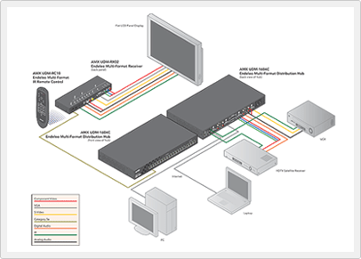
 Diagram Diagram |
 |

